

1. Tools & Equipment Needed
-
NIST-traceable pressure calibrator (hydraulic hand pump + reference gauge, or deadweight tester)
-
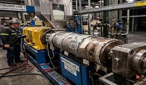
Temperature-controlled barrel/extruder (must be at normal operating temperature)
-
Multimeter or calibration reader (for mV/mA/V sensors)
-
Portable calibrator/communicator (for smart transmitters w/ HART, Profibus, etc.)
-
Clean lint-free wipes and approved cleaning tools for sensor port
-
Calibration log sheet or digital CMMS entry system
2. Preparation
☐ Verify that the process barrel is heated to normal operating temperature.
☐ Remove material pressure from the barrel (ensure extruder screw is idle).
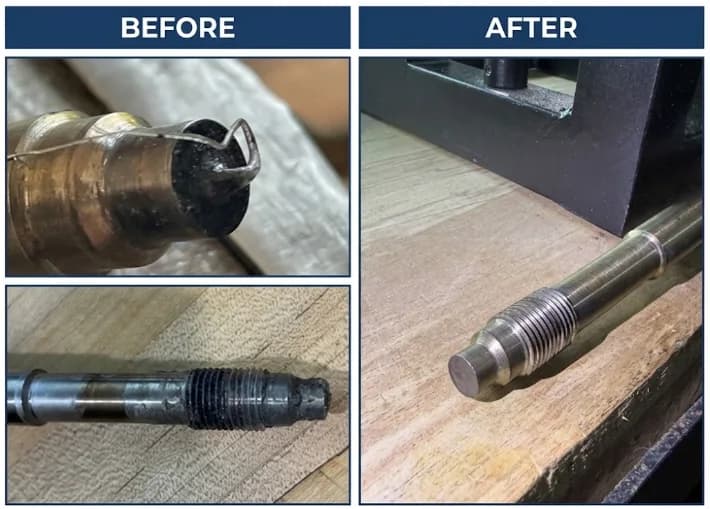
☐ Inspect sensor port for debris, damage, or leftover polymer—clean if necessary.
☐ Confirm reference calibration device is within valid certification date.
☐ Allow sensor to stabilize for 20–30 minutes at operating temperature.
3. Zero Calibration
For all sensor types
☐ With no material pressure on the diaphragm:
-
Set controller/indicator to 0 psi (0 bar).
-
If using a transmitter, adjust zero trim.
-
For digital transmitters, use “Zero Trim” in software/communicator.
☐ Record the zero value in the log sheet.
4. Span Calibration
A. Strain Gauge / mV Output Transducers
☐ Connect calibrator and apply a known reference pressure (e.g., 5,000 psi).
☐ Measure mV signal and compare to expected value (e.g., 2 mV/V output).
☐ Adjust gain/scale on controller so displayed reading matches reference.
B. Amplified Transmitters (mA or V)
☐ Apply reference pressure.
☐ Verify output:
-
4 mA (or 0 V) = 0 psi
-
20 mA (or 10 V) = full-scale psi (e.g., 10,000 psi) ☐ Adjust span trim until transmitter output matches reference pressure.
C. Smart Digital Transmitters
☐ Use communicator to run Zero Trim at no pressure.☐ Apply reference pressure OR simulate span test electronically.☐ Adjust Span Trim digitally to align with standard.
5. Validation
☐ Remove pressure and verify that reading returns to zero.
☐ Apply intermediate pressure point (25% or 50% FS) and confirm linearity.
☐ Repeat for 75% FS.
☐ If non-linear, investigate sensor damage or port blockage.
6. Documentation
☐ Record:
-
Sensor ID / location
-
Date & technician
-
Reference equipment used (serial #, calibration due date)
-
Zero & span results (before and after adjustment)
-
Pass/Fail status
☐ Store records in calibration logbook or CMMS system.
7. Frequency Guidelines
-
Plastics extrusion: - Quick zero check → daily or after each cleaning - Full calibration → every 6 months
-
Food processing: - Zero check → weekly/startup - Full calibration → every 3 months (per audit requirements) - Annual factory re-calibration
GOAL: A transducer/transmitter with traceable, verified accuracy for both quality and compliance.
Comment for your PDF Printable Checklist Today
Make the next step a confident one.
Share your part number or process requirements. We’ll help you work through the fit.
Talk to an expert